General concepts
Courses
Basic theory
Naming
In a robot arm, there are two main types of components: joints and links.
There are two types of joints: revolute joints and prismatic joints. Each joint provides 1 degree of freedom (DoF), allowing rotation or translation along a specific axis.
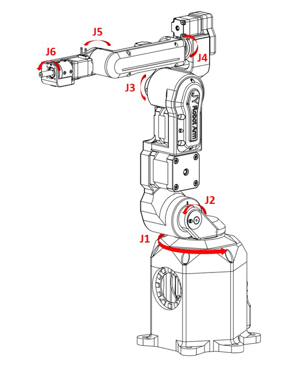
Links are rigid bodies that connect to joints. The naming convention starts with "Link 0," which is stationary, and continues with "Link 1" connecting to the previous link, and so forth.
Here is a simplified image illustrating the joints and links of a robot arm:

Right hand rule (右手定則)
The right-hand rule is a convention used to define the orientation of coordinate systems in three-dimensional space. Here are two typical gesturing:
- Thumb (x-axis), Index Finger (y-axis), Middle Finger (z-axis)
- Thumb (z-axis), Index Finger (x-axis), Middle Finger (y-axis)
Robot pose
In the realm of robotics, "pose" refers to the complete description of a robot's position and orientation within its environment. It provides a comprehensive understanding of where the robot is situated and how it is aligned relative to a specific coordinate system or frame of reference. A robot's pose has:
-
Position (x, y, z): This denotes the precise location of the robot in the surrounding environment.
-
Orientation (α, β, γ) / (ψ, θ, φ): This specifies the orientation or rotational aspect of the robot in space. There are two main methods for representing rotation in 3D space: Fixed angles and Euler angles.
The combination of position and orientation fully characterizes the robot's pose at a specific point in time. In 3D space, there are 3 degrees of freedom (DoF) for position and 3 DoF for rotation, resulting in a total of 6 DoF. This explains why most robot arms are designed with 6 DoF. If a robot arm possesses more than 6 DoF, it is considered to have redundant DoF.
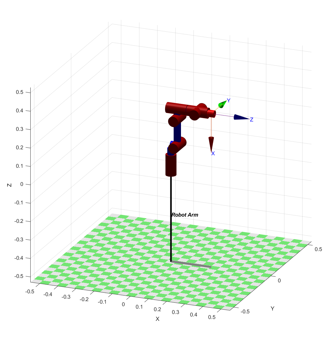
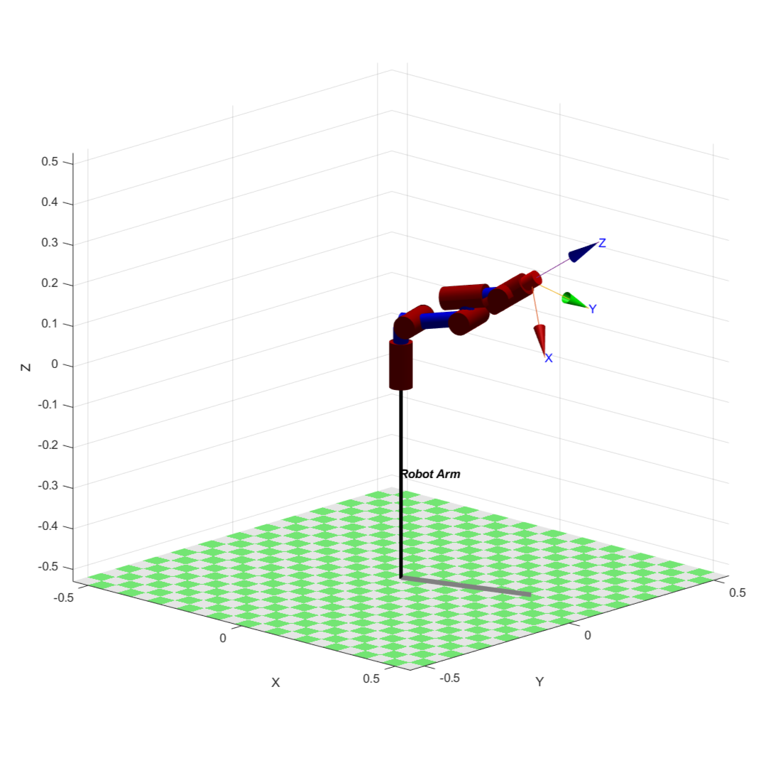
To run the simulation, please download the robotics toolbox for Matlab.
Here is the code for the robot.
Kinematic diagram
A kinematic diagram of a robotic arm is a simplified graphical representation that illustrates the arrangement of links and joints in the robotic arm. It serves to convey the essential geometric and kinematic relationships between the various components of the arm without necessarily capturing all the physical details.
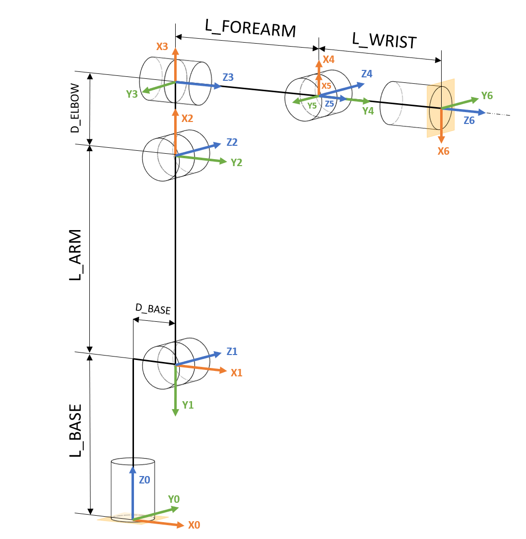
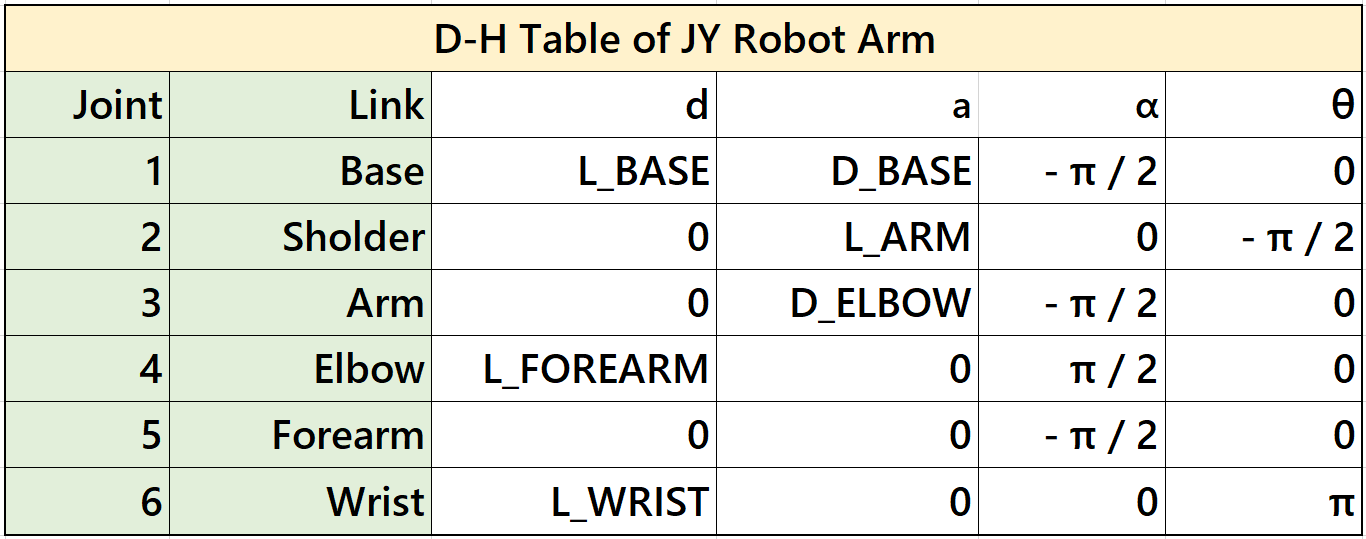
Denavit-Hartenberg (D-H) parameters
It is essential to define transformation matrix between each joints. With these matrixes, we can transform the frame from the base to any joint or the end-effector. Then, we will know where them are in the environment. That's why we need a standardized way to define these matrixes.
D-H parameters are a set of parameters used to describe the geometry and kinematics of robotic arms and mechanisms. It is a systematic way to represent the transformation between consecutive coordinate frames along a robot's kinematic chain.
The D-H parameters consist of four values associated with each joint of a robotic arm:
-
Link Length (a): The distance between the common normal (perpendicular) to the current and next joint axes, measured along the previous joint axis.
(distance between \(\^{Z}_{i-1}\) and \(\^{Z}_{i}\) along \(\^{X}_{i-1}\))
-
Link Twist (α): The angle between the common normal of the current and next joint axes, measured along the previous joint axis.
(angle between \(\^{Z}_{i-1}\) and \(\^{Z}_{i}\) along \(\^{X}_{i-1}\))
-
Link Offset (d): The distance between the joint axes along the common normal, measured along the current joint axis.
(distance between \(\^{X}_{i-1}\) and \(\^{X}_{i}\) along \(\^{Z}_{i-1}\))
-
Joint Angle (θ): The angle of rotation or translation about the current joint axis to align the coordinate frames.
(angle between \(\^{X}_{i-1}\) and \(\^{X}_{i}\) along \(\^{Z}_{i-1}\))
These parameters are defined for each pair of consecutive joints in the robot's kinematic chain. By applying a sequence of transformations using these parameters, we can calculate the overall transformation matrix that represents the position and orientation of each link relative to a reference frame.
Reference Frames (參考座標系)
Coordinate frames or axes are often included at each joint to show the orientation and position of each joint relative to a common reference frame. These frames help in defining the transformations between different segments of the arm.
-
World reference frame (WRF) This is a static frame that is fixed in real world. It is usually located in the base of the robot.
-
Tool reference frame (TRF) Reference frame that is associated to robots end-effector. It is depicted in the video below:
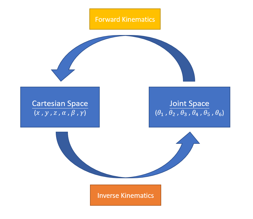
Forward kinematics
Forward kinematics involves determining the position and orientation of a robot's end effector based on the known joint angles and link parameters. In simpler terms, it's the process of calculating the robot's pose in space given the joint configurations.
\((\theta_1, \theta_2, \theta_3, \theta_4, \theta_5, \theta_6) \rightarrow (x, y, z, \alpha, \beta, \gamma)\)
Inverse kinematics
Inverse kinematics involves determining the joint angles or parameters of a robotic mechanism in order to achieve a desired end-effector position and orientation. In simpler terms, it's the process of calculating the joint configurations that will result in a specific pose of the robot's end-effector.
Inverse kinematics can be quite complex, especially for robots with multiple joints and degrees of freedom. Solving inverse kinematics involves finding solutions to sets of nonlinear equations that relate the joint variables to the desired end-effector pose. Depending on the robot's geometry and the specific task at hand, there may be multiple solutions, a unique solution, or even no solution.
One method to simplify solving inverse kinematics is Pieper's Solution. If the axes of the last 3 DoF of the robot arm intersect at a single point, Pieper's Solution can be applied. The basic idea is to use the first 3 DoF to generate position and the last 3 DoF to generate orientation, which can be decoupled from position since the last 3 DoF intersect at a single point. For detailed mathematics, refer to Pieper's Solution.
Cartesian space and Joint space
The image below illustrates the relationship between Cartesian space and joint space. It also demonstrates how inverse kinematics and forward kinematics work between these two spaces.
Singularity
When a robot navigates through Cartesian space, challenges arise at singularities, which occur when joints reach their limits or when two or more joints align collinearly.
At these joint alignments, certain movements within Cartesian space become unattainable, leading to exceedingly high joint velocities. The mathematical equations governing the robot's motion approach singularity when divided by small values. The actual singularity manifests when one of these equations is divided by zero, signifying the impossibility of the movement.
Singularity point represent critical zones where the robot's kinematic equations encounter mathematical limitations due to specific joint configurations, resulting in movement impossibilities or erratic behavior.