Electronics
For the basic usage of the robot arm, we need 3 type of boards: REF control board 42 motor control board (for NEMA 17 motors) 20 motor control board (for NEMA 8 motors)
And we will dive into the details of each board in the following sections.
REF
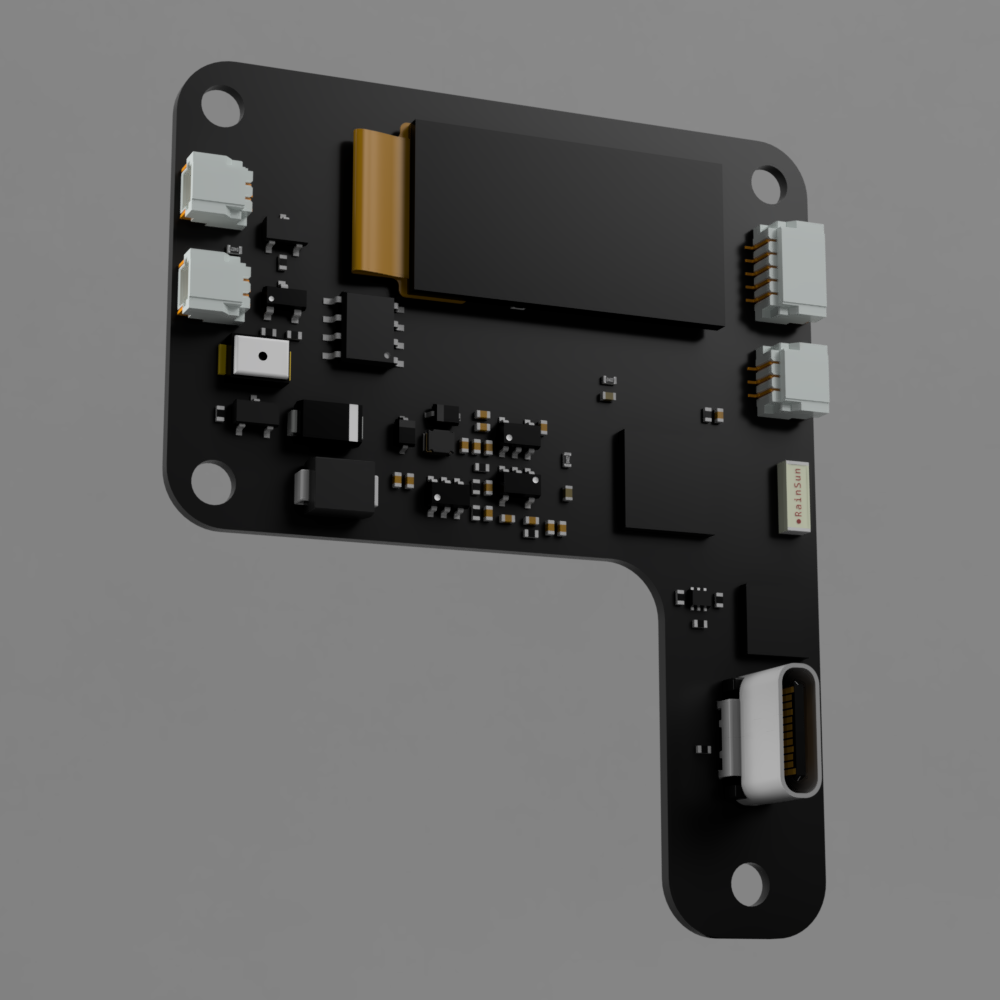
- REF board render image
- REF board front side and back side spec
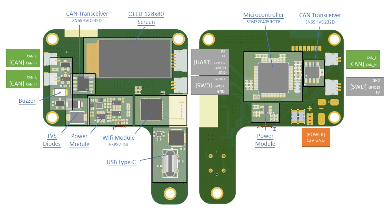
Hardware specs
| Main processor | STM32F405RGT6 |
| Main processor features | Arm® 32-bit Cortex®-M4 CPU with FPU, Adaptive real-time accelerator |
| Main Processor memory | 1 Mbyte of Flash memory, 196 Kbytes of SRAM |
| Minor Processor | ESP32-PICO-D4 |
| Minor processor features | single 2.4G Hz Wi-Fi and Bluetooth combo chip |
| Communication interfaces | 3 x CAN bus, 1 x UART, 3 x GPIO, 1 x USB TYPE-C |
| CAN tranceiver | SN65HVD232DR |
| USB processor | CP2102 |
| Display | OLED 128x80 screen |
| Programming interface | SWD |
| Buck module | ME1336 (5V), LP2992 (3V3) |
Operating limits
| Power supply | 9V minimal, 12V maximal voltage |
| On board operating voltage | 3.3V, 5V |
| Current | Max 2A |
Motor-20 & Motor-42
Motor-20 and Motor-42 boards are basically the same but with some minor differences.
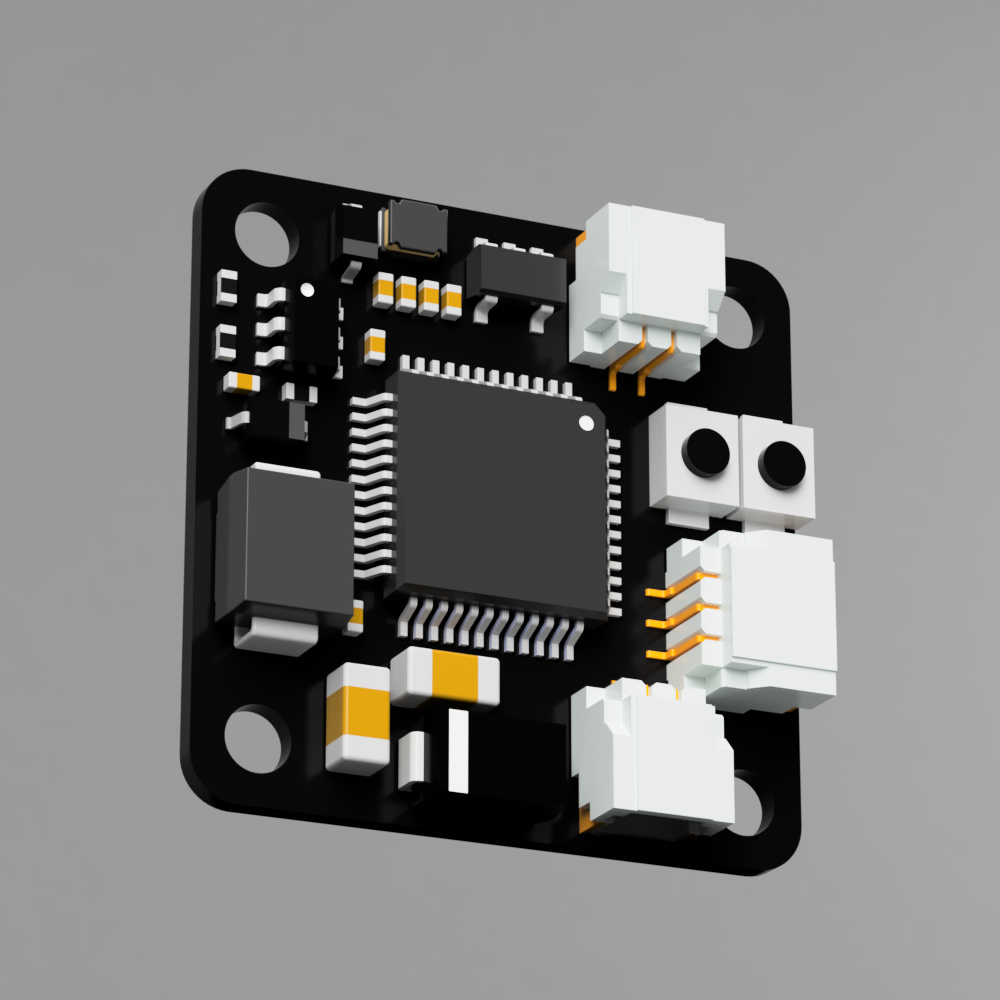
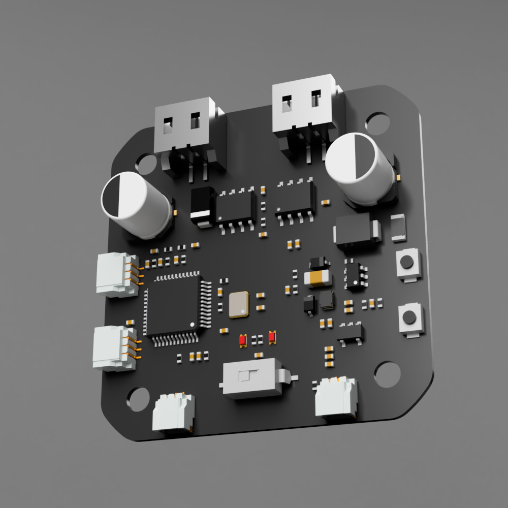
- Motor-20 board render image
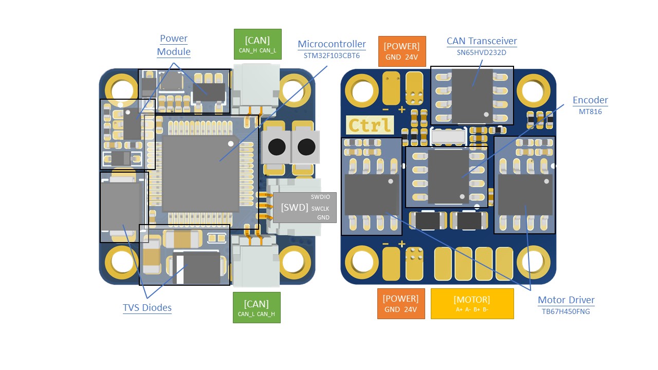
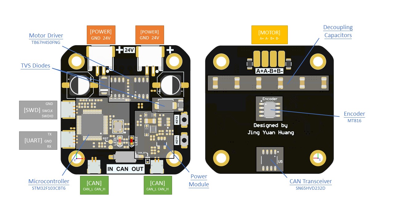
- Motor-20 board front side and back side spec
- Motor-42 board render image
- Motor-42 board front side and back side spec
Hardware specs
| Processor | STM32F103CBT6 |
| Processor features | Arm® 32-bit Cortex®-M3 CPU core – 72 MHz maximum frequency |
| Communication interfaces | 2 x CAN bus |
| CAN tranceiver | SN65HVD232DR |
| Stepper drivers | TB67H450FNG |
| Stepper drivers features | PWM, 50V, 3.5A max |
| Programming interface | SWD |
Operating limits
| Power supply | 18V minimal, 24V maximal voltage |
| Current | Rated current 2.5A, maximal current 3.6A |
Physical properties
Dimensions
- REF board (mm)
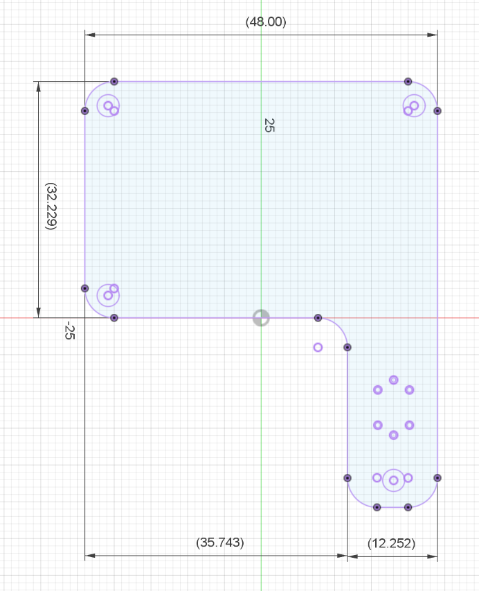
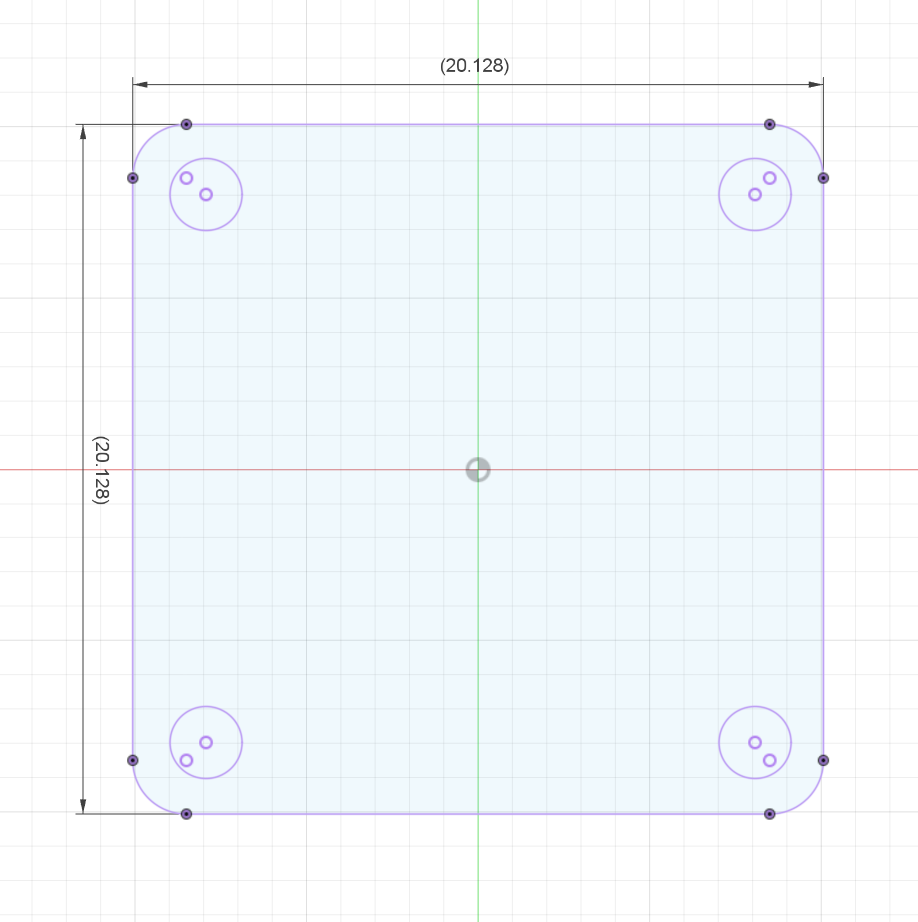
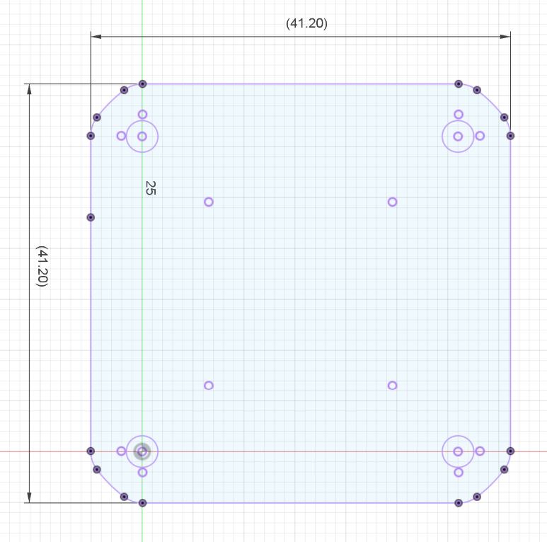
- Motor-20 board (mm)
- Motor-42 board (mm)
3D CAD models
Connections
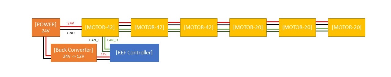
The connection diagram is shown in below. This is a series connection and each PCB has 4 lines (VCC, GND, CAN_H, CAN_L) connect to it.
Connectors
- REF
- SH 1.0 2P (CAN bus)
- SH 1.0 3P (SWD)
- Motor-42
- SH 1.0 2P (CAN bus)
- SH 1.0 3P (SWD)
- PH 2.0 2P (POWER)
- Motor-20
- SH 1.0 2P (CAN bus)
- SH 1.0 3P (SWD)
- Dupont 2P (POWER)
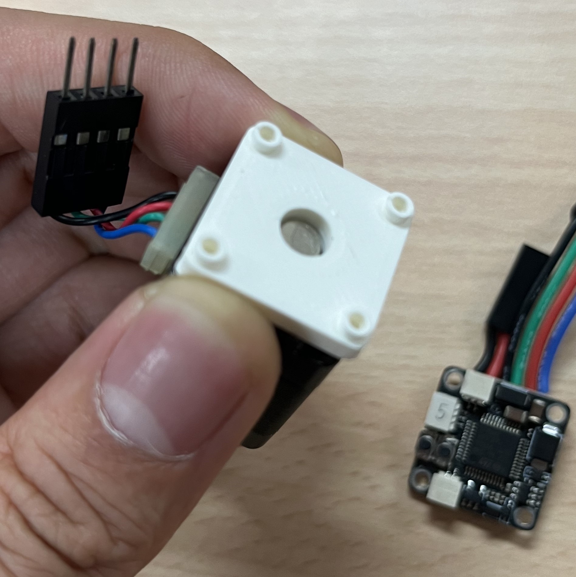
Attach driver to stepper motors
This step is crucial in the construction of the robot arm.
The encoder, a magnetic sensor, is soldered onto the center of the PCB. To ensure accurate homing and control of the stepper motor, magnets need to be attached to the motor axis. The quality of this installation directly affects the functionality of the system.
Magnets
!!! The magnets need to be radial magnetization !!!
- Motor-20: D5 x 1.5 * 5 (mm)
- Motor-42: D7 x 1.5 * 2 (mm)
Isolation
Installation
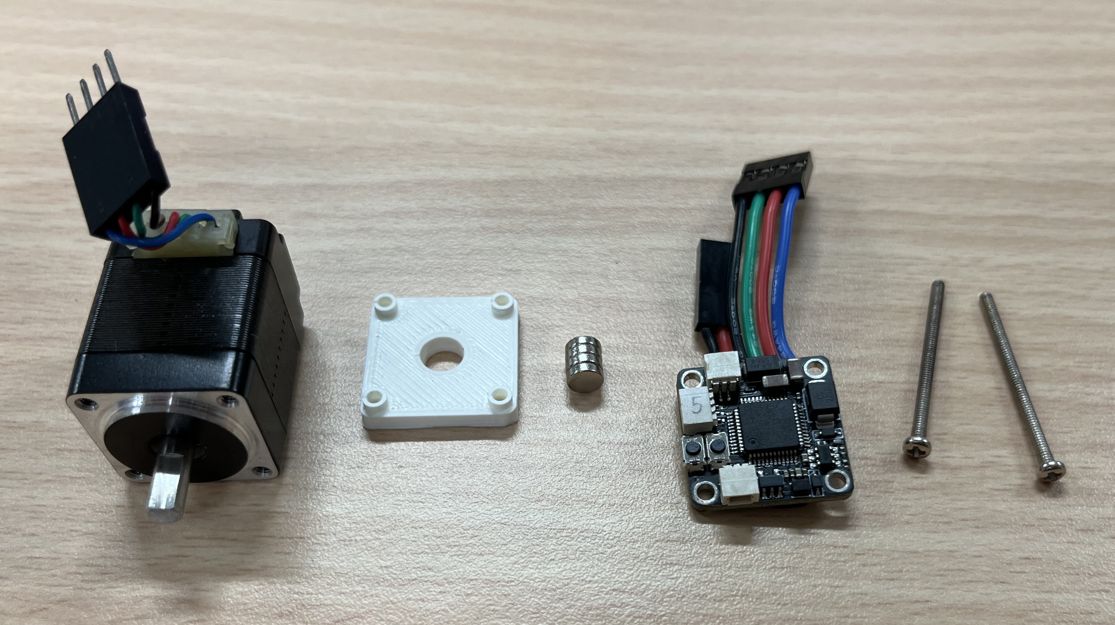
Let's take Motor-20 for example. Here is the full view of all the components. Use fast dry glue to glue magnet to the end of stepper motor axis.
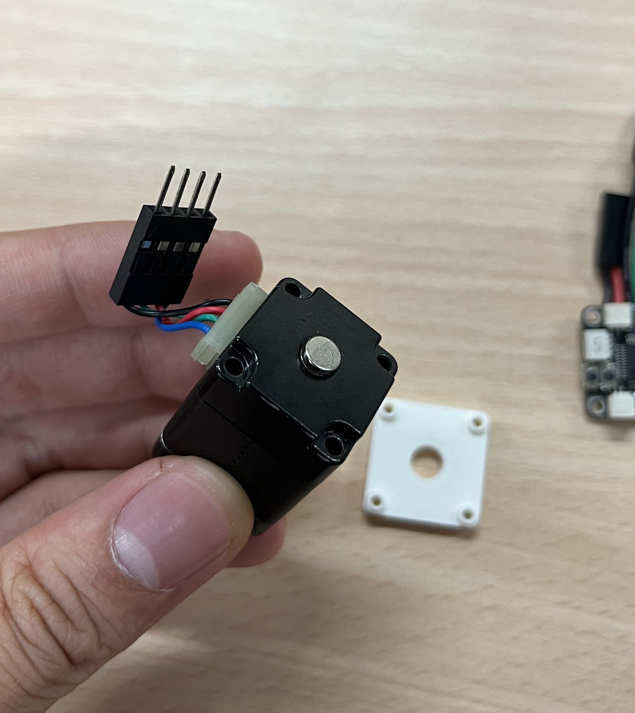
Then, let's install isolation shield and motor driver on the back of the motor.
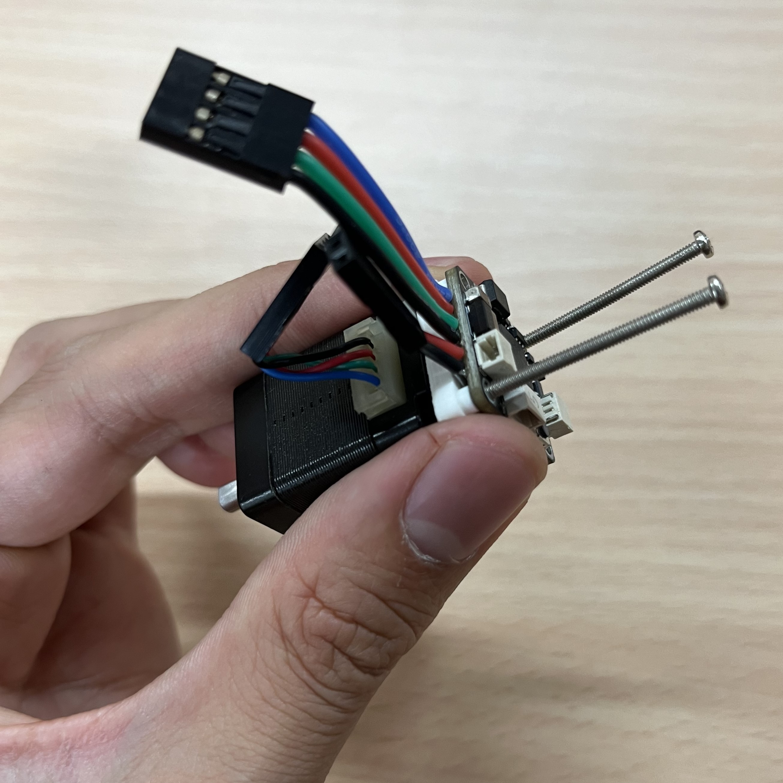
Repeat this process to all the motors and we're ready to go to wiring and test.
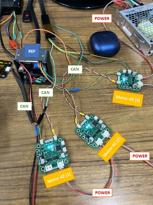
Wiring
Follow this diagram to wire your Motor driver board to REF control board.
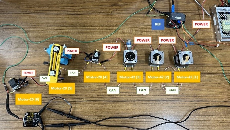
After sucesssful wiring of the robot it should look something like this.
- Wiring with 3 Motor-42 boards
- Wiring with 3 Moto-42 boards and 3 Motor-20 boards
- 3 motors testing video
- Full setup testing video