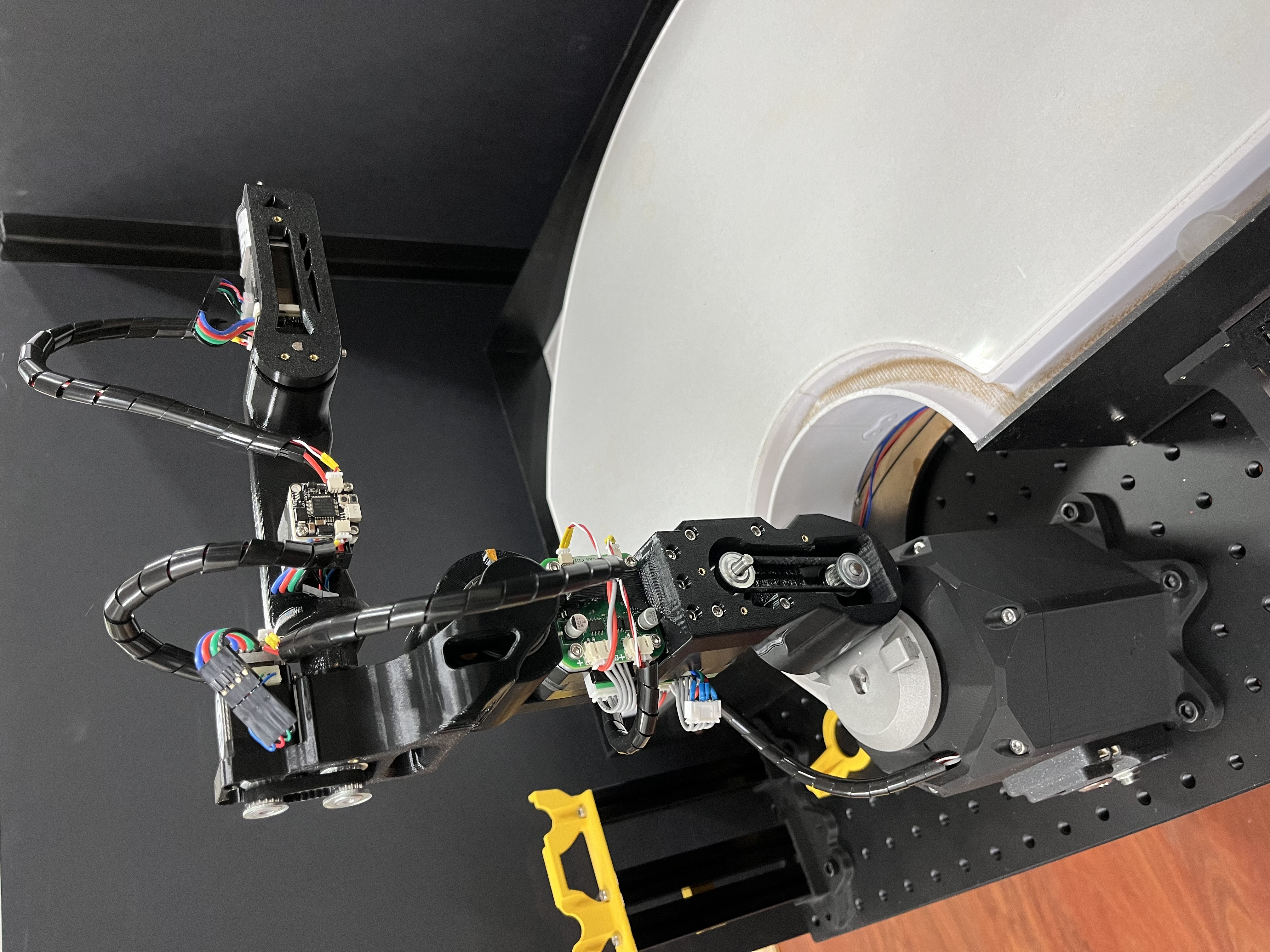
Mechcanical assembly
This section covers the maintenance of the mechanical structure, replacement of 3D-printed parts, and assembly of the robot arm.
BOM
Before assembly, ensure all components are ready (screws not included):
-
Base:
- REF
- PCB
- LM2596 (pretune 24V -> 12V)
- Metal LED latching 16mm power push button ON-OFF switch 12V
- DC-5V Jack
-
Harmonic drive
-
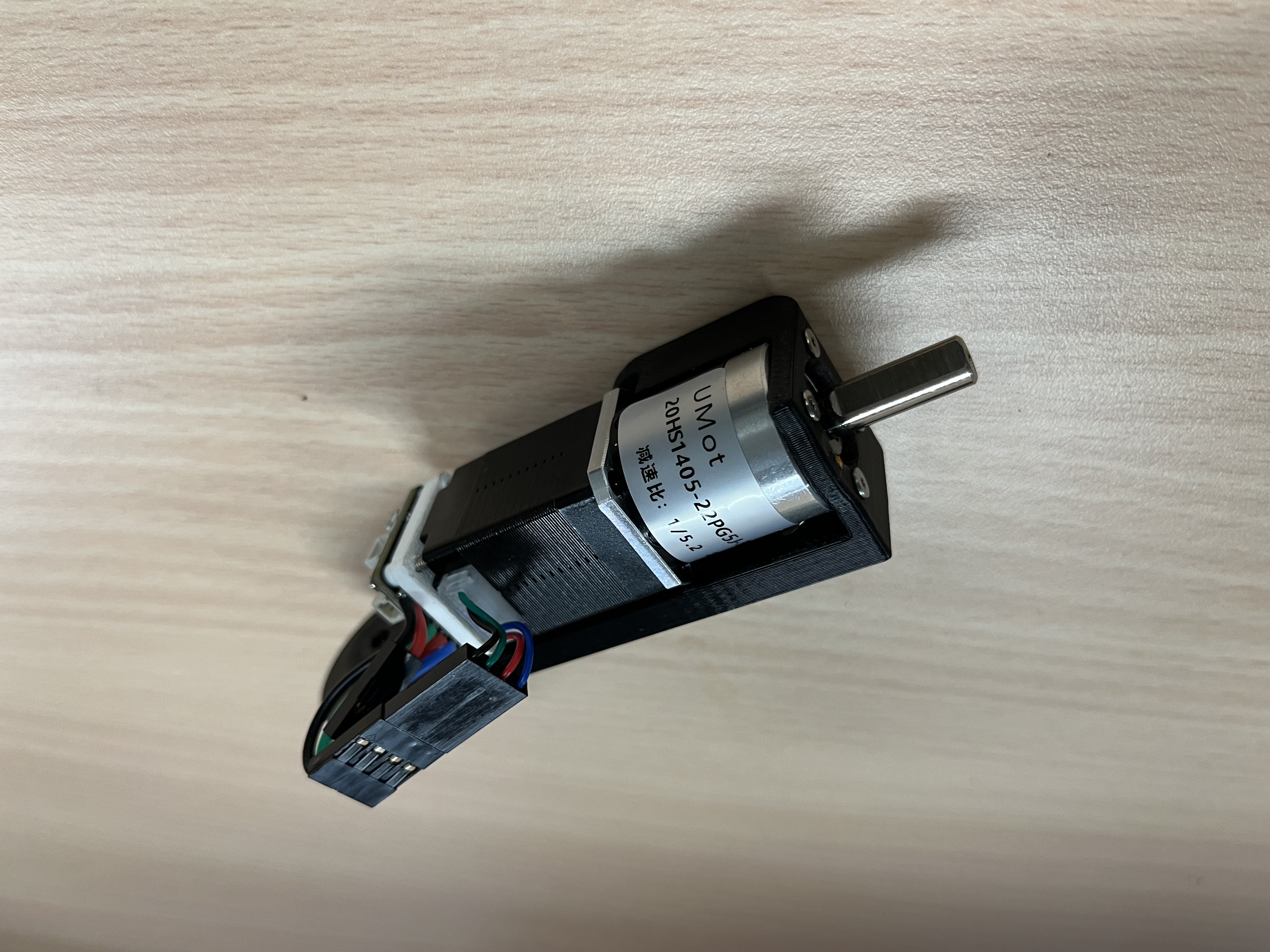
Stepper motor and control board
- NEMA 17 Bipolar Stepper Motor (17HS16-2004S1)
- Motor-42 board
- Coupler (hole: 5mm to 8mm, height: 25mm)
- Housing listed in [Specification -> Mechanical]
- REF
-
Shoulder:
- Bearing
- 20307-2RS (20x30x7)
- BA3047 (30x47x2)
- Housing listed in [Specification -> Mechanical]
- Bearing
-
Arm:
-
Stepper motor and ctrl board
- NEMA 17 Bipolar Stepper Motor (17HS16-2004S1)
- NEMA 17 Bipolar Stepper Motor Pancake (17HS10-0704S)
- Motor-42 board * 2
-
Harmonic drive
-
Bearing
- 63705zz (25x32x7) * 2
-
Pulley and belt
- GPA20GT2040-A-H5 * 4
- 150mm belt ring
- 116mm belt ring
-
Housing listed in [Specification -> Mechanical]
-
-
Elbow:
-
Stepper motor and ctrl board
- NEMA 8 Bipolar Stepper Motor (8HS11-0204S)
- Motor-20 board
-
Harmonic drive
-
Bearing
- ET2015 (15x20x3.5) * 2
-
Pulley and belt
- GPA16GT2040-A-H3
- GPA16GT2040-A-H4
- 78mm belt ring
-
Housing listed in [Specification -> Mechanical]
-
-
Forearm:
-
Stepper motor and ctrl board
- NEMA 8 Bipolar Stepper Motor (8HS11-0204S)
- Motor-20 board
-
Harmonic drive
-
Bearing
- ET2015 (15x20x3.5)
-
Pulley and belt
- GPA16GT2040-A-H3
- GPA16GT2040-A-H4
- 176mm belt ring
-
Housing listed in [Specification -> Mechanical]
-
-
Wrist:
-
Stepper motor and ctrl board
- NEMA 8 Bipolar Stepper Motor (8HS11-0204S) with Gearbox (1:5.2)
- Motor-20 board
-
Housing listed in [Specification -> Mechanical]
-
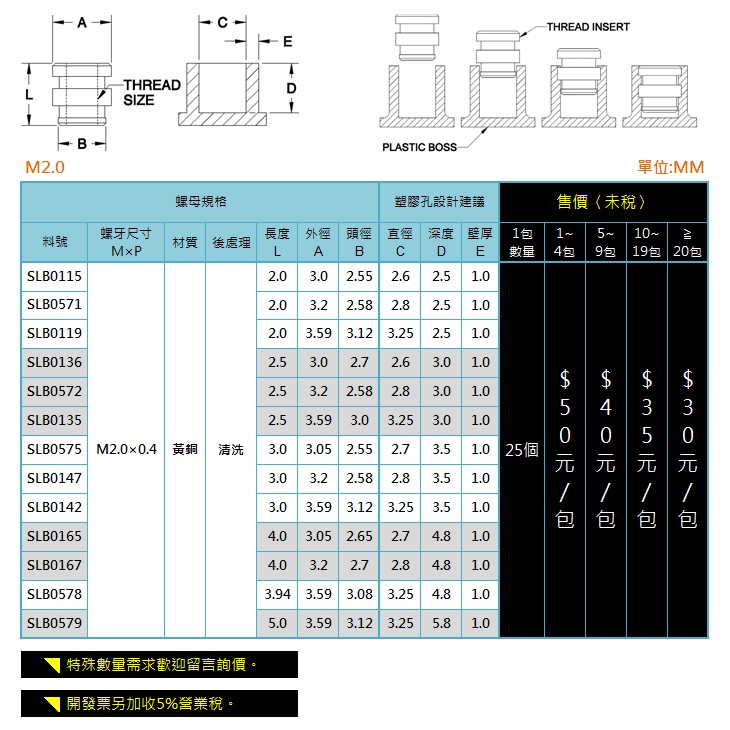
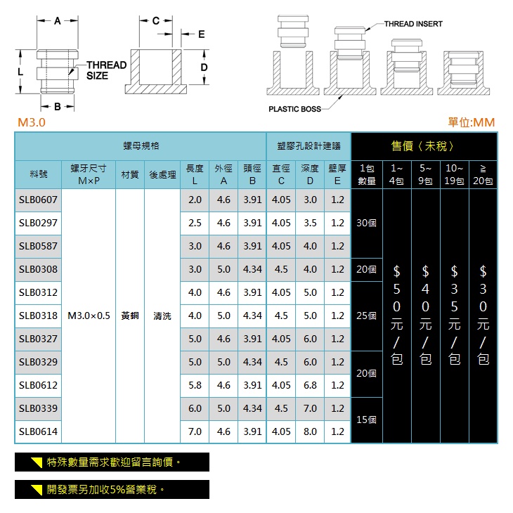
Heat inserts
Before assembly, insert heat inserts into 3D-printed parts. You'll need 17 * M2 Heat inserts (SLB0115) and 3 * M3 Heat inserts (SLB0297).
- example
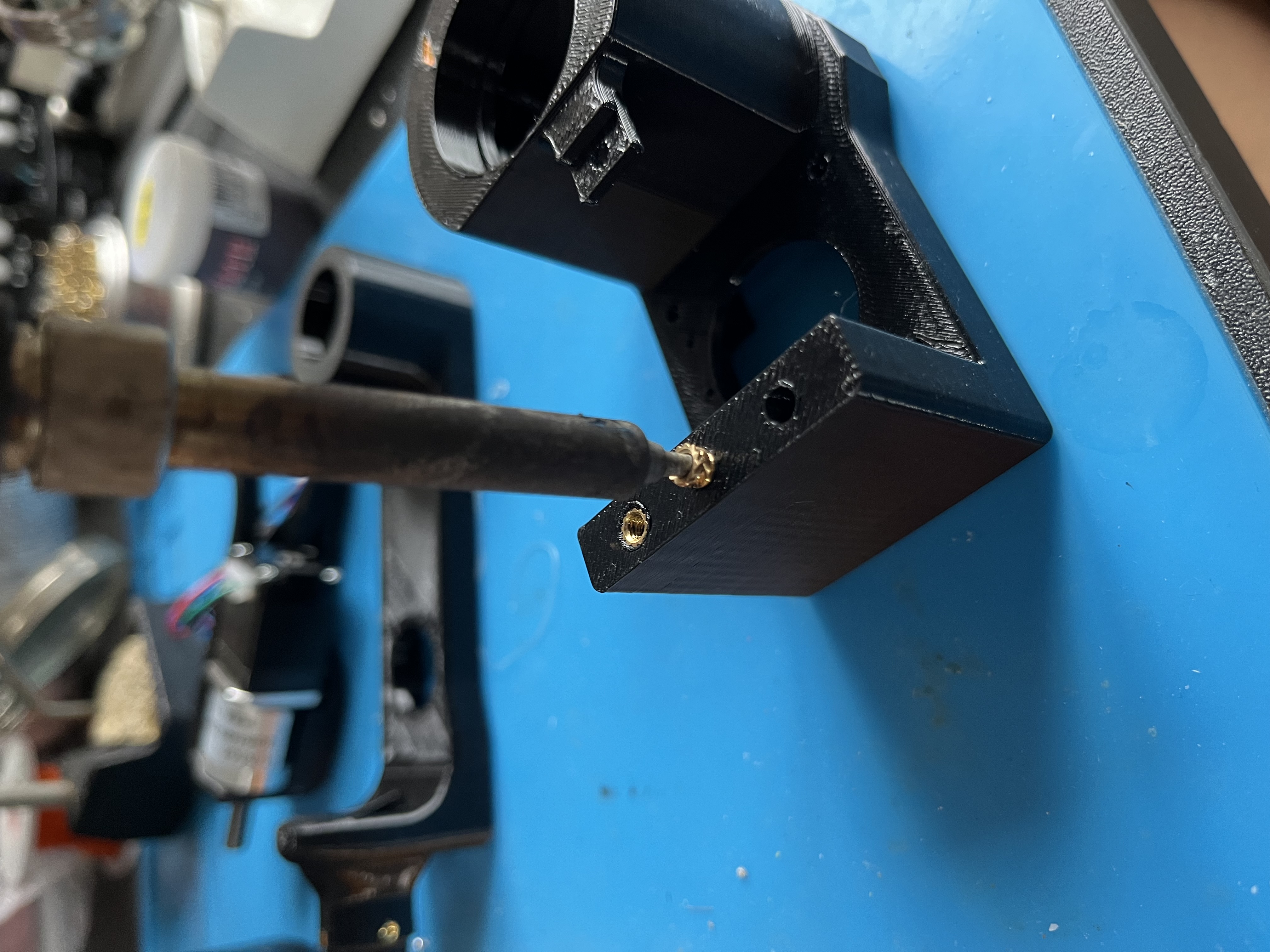
- specification of M2, M3 heat insert
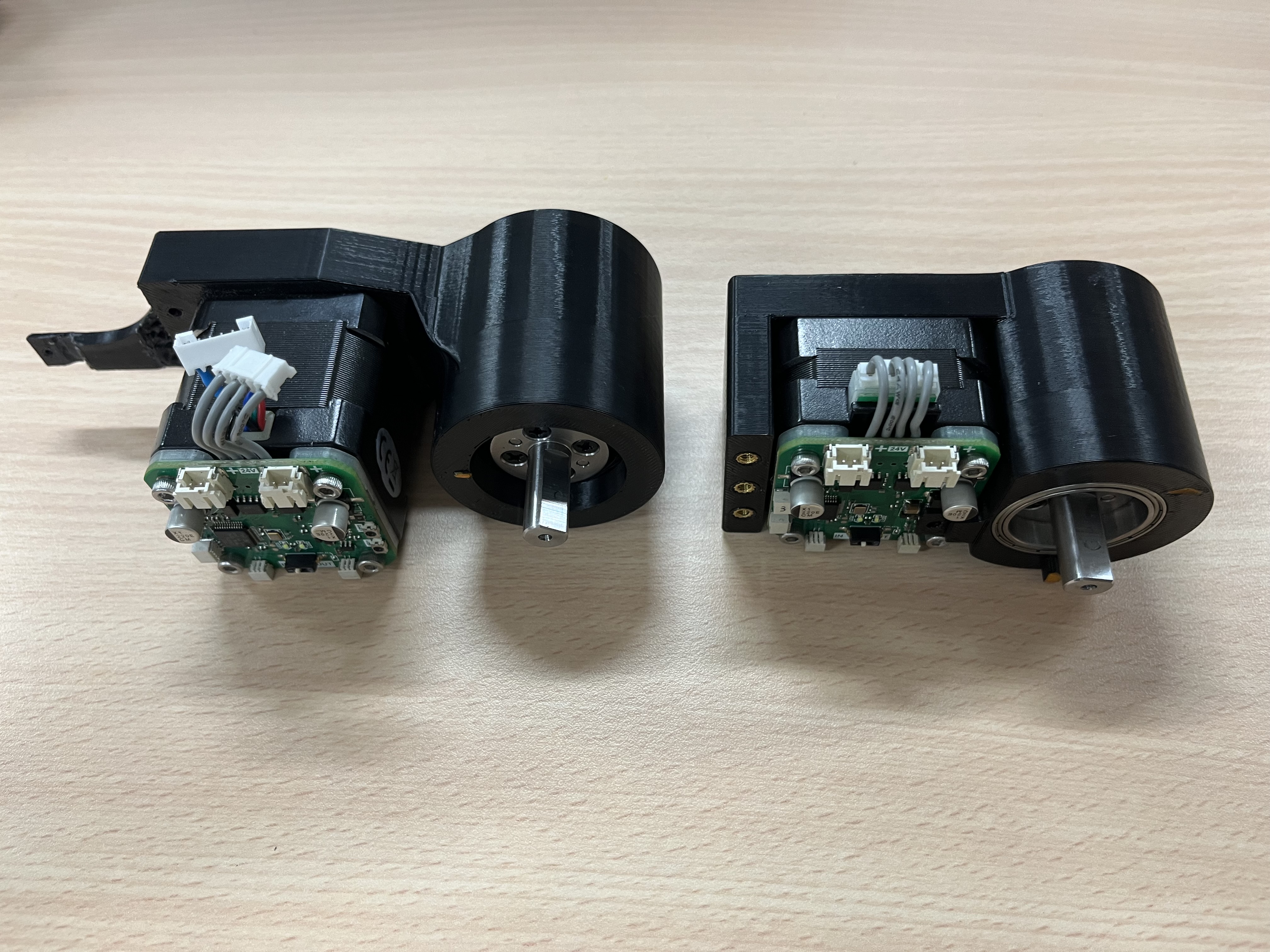
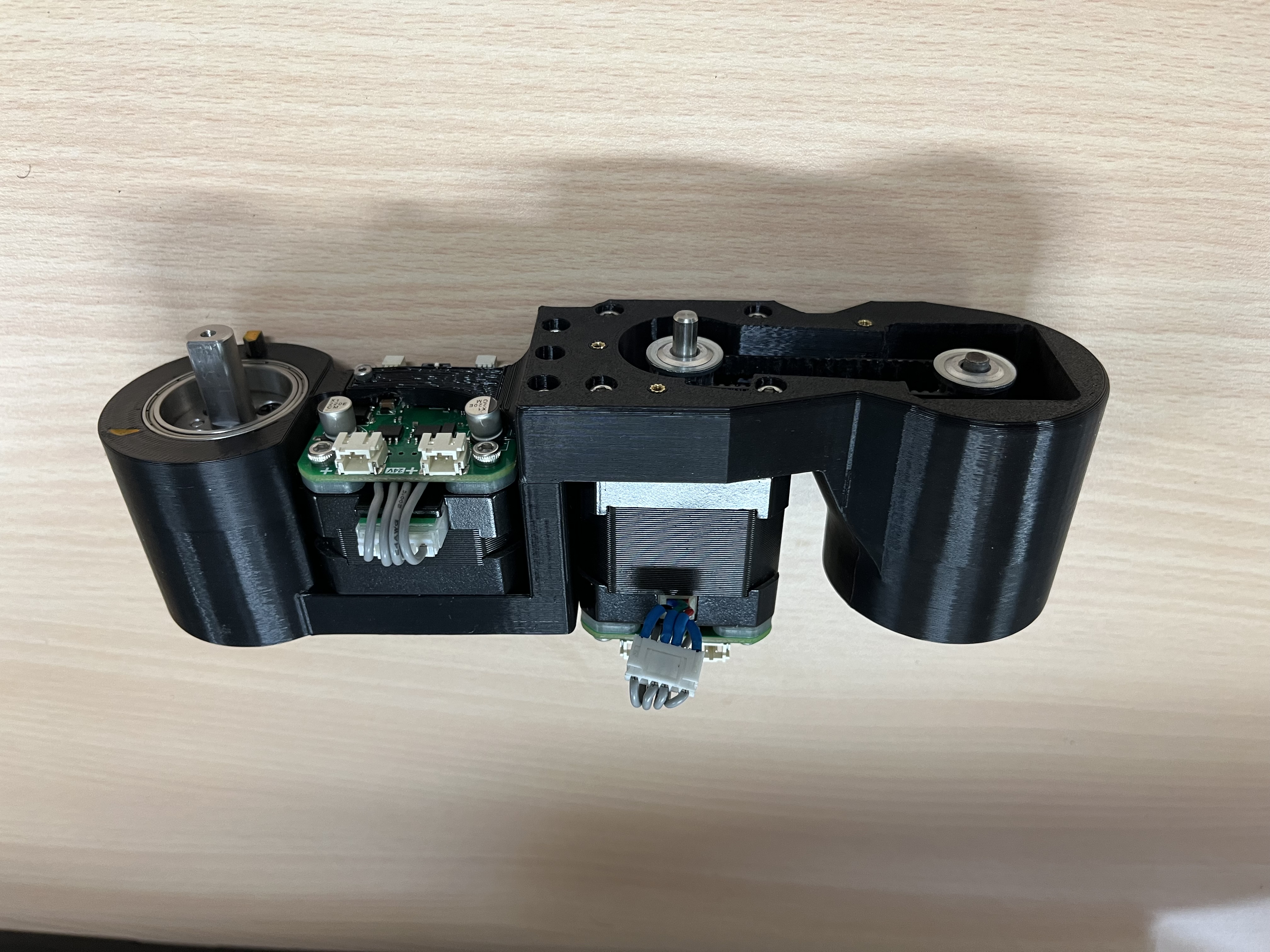
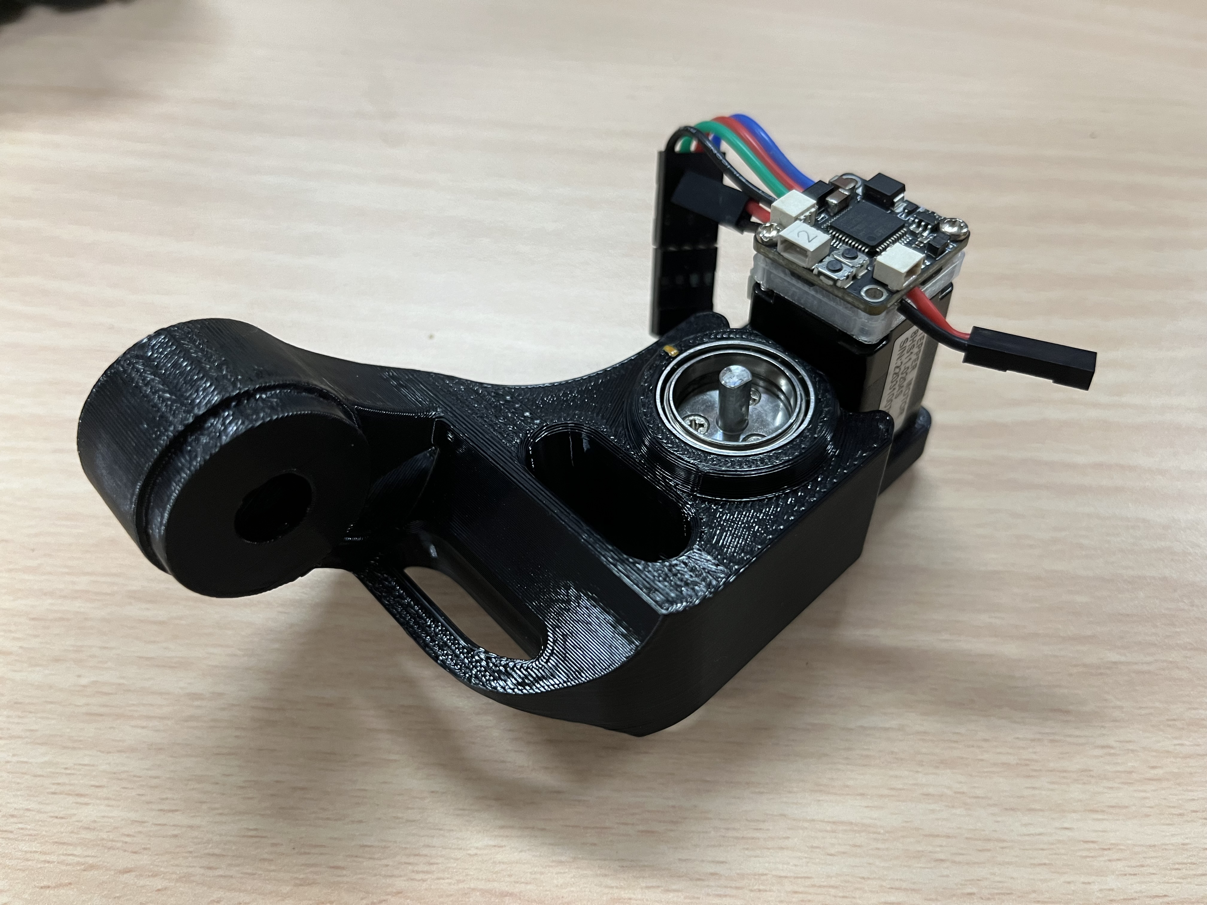
Motors and gearboxes
Fix motors and gearboxes to the housing.
Note: The harmonic drive needs to be interference-fit to the housing, making it slightly challenging to slide into place. Use a C-clamp to gradually push them in. If needed, lightly sand the wall, but be careful not to sand too much.
- Arm (M3 x 11 * 4, M3 x 10 * 4)
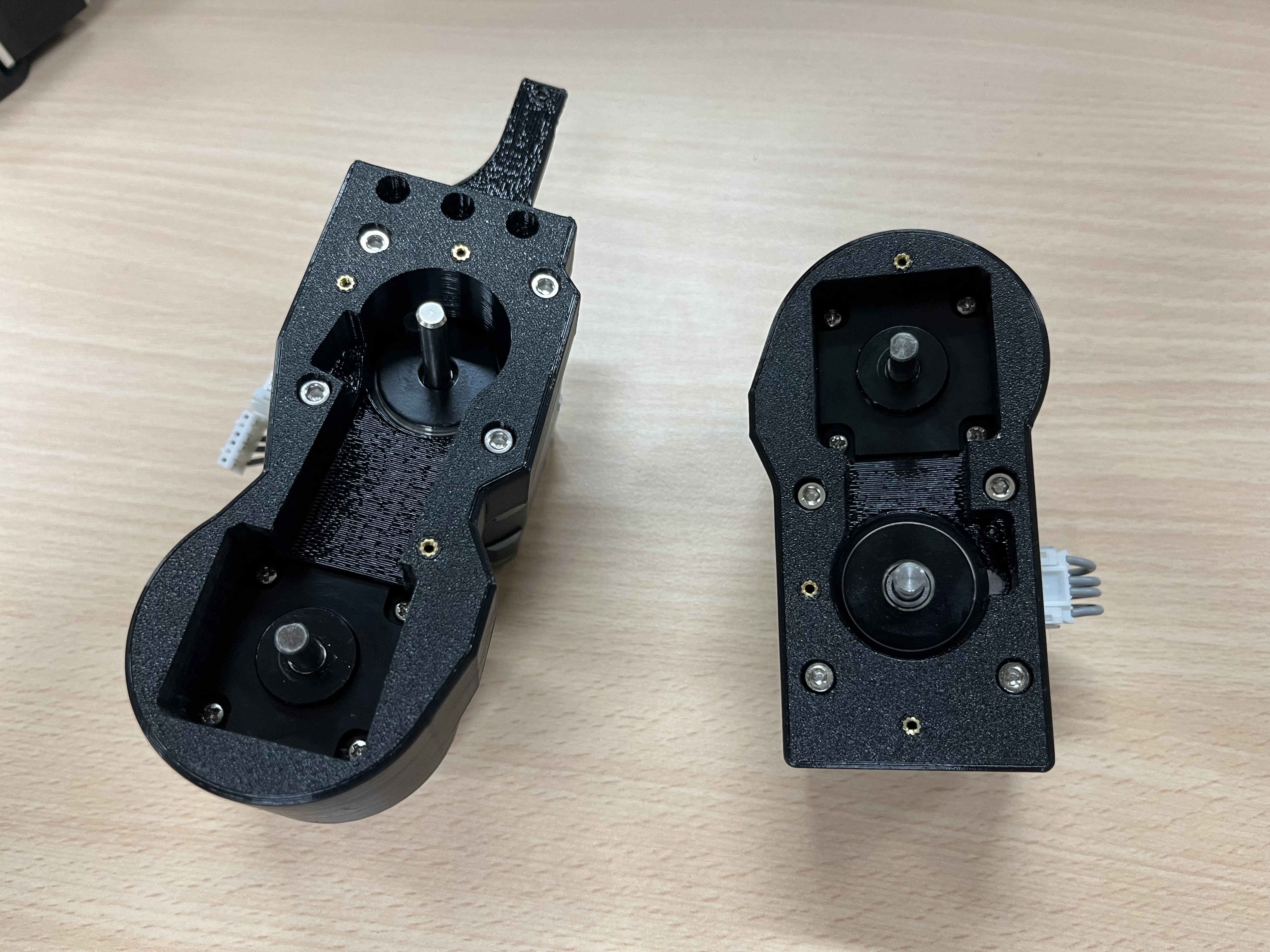
- Fix arm_top and arm_bottom together (M3 x 20 * 3)
- Elbow (M2 x 6 * 4)
- Forearm (M2 x 6 * 4)
- Wrist (M2 x 6 * 4)
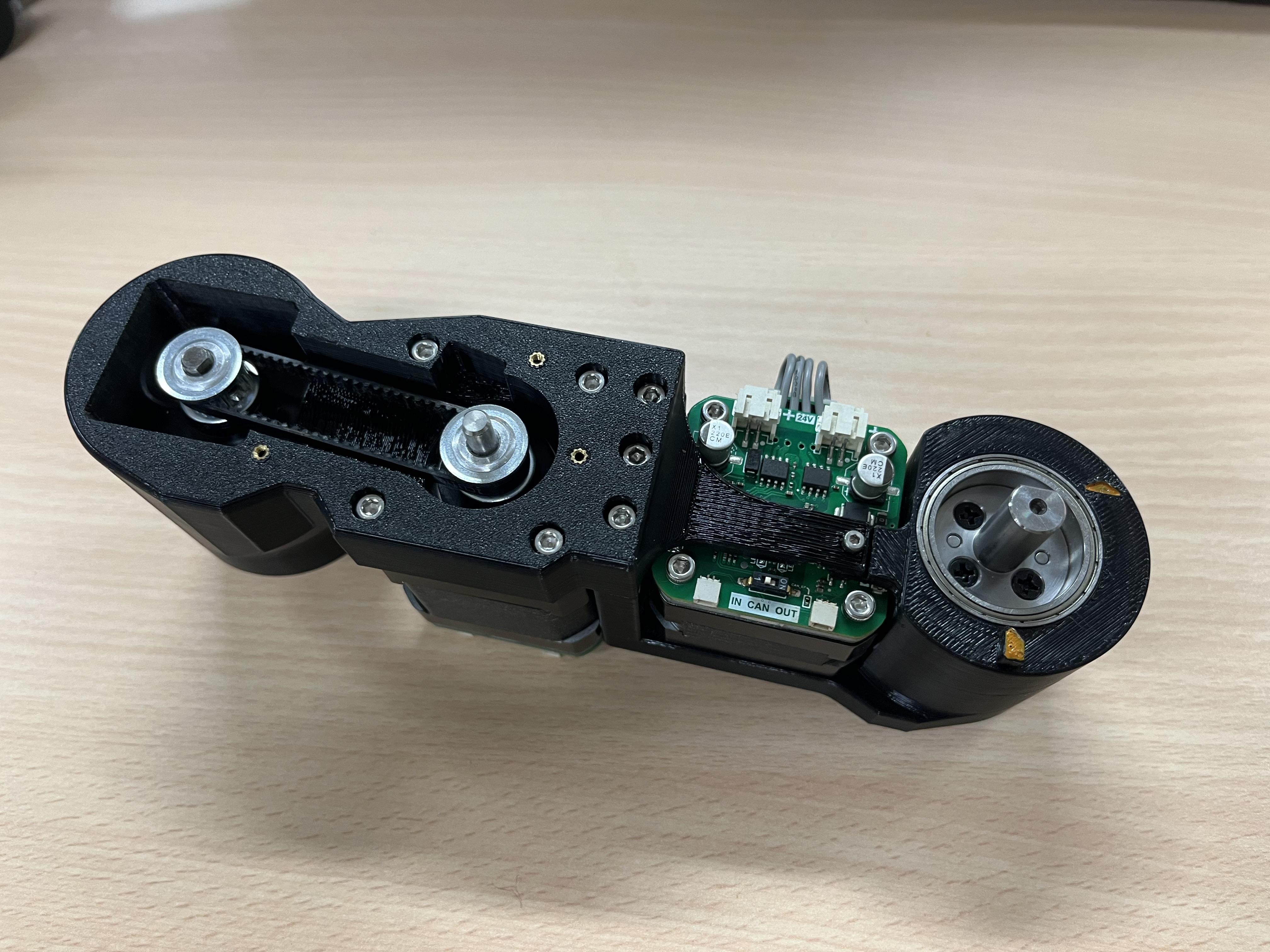
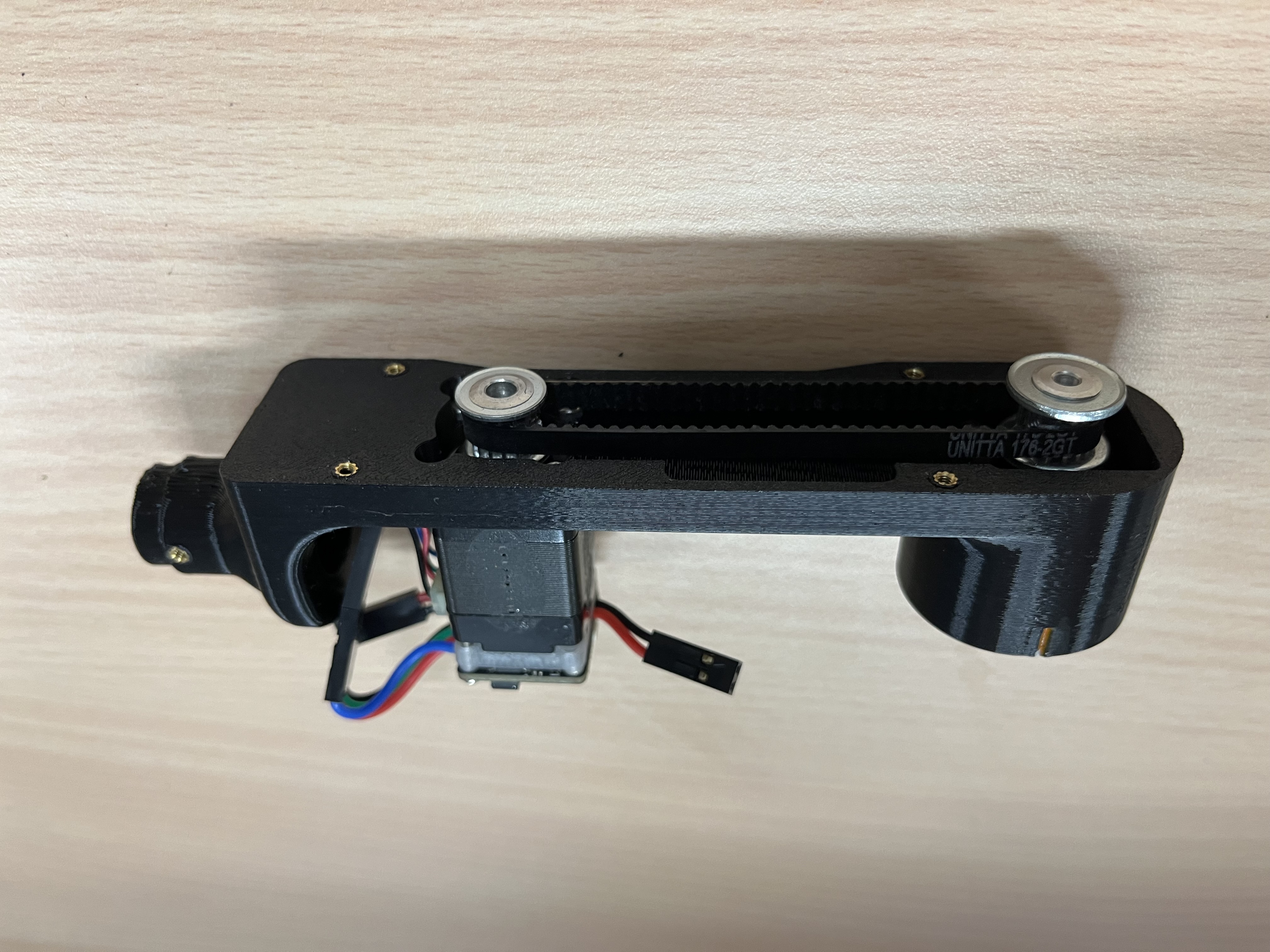
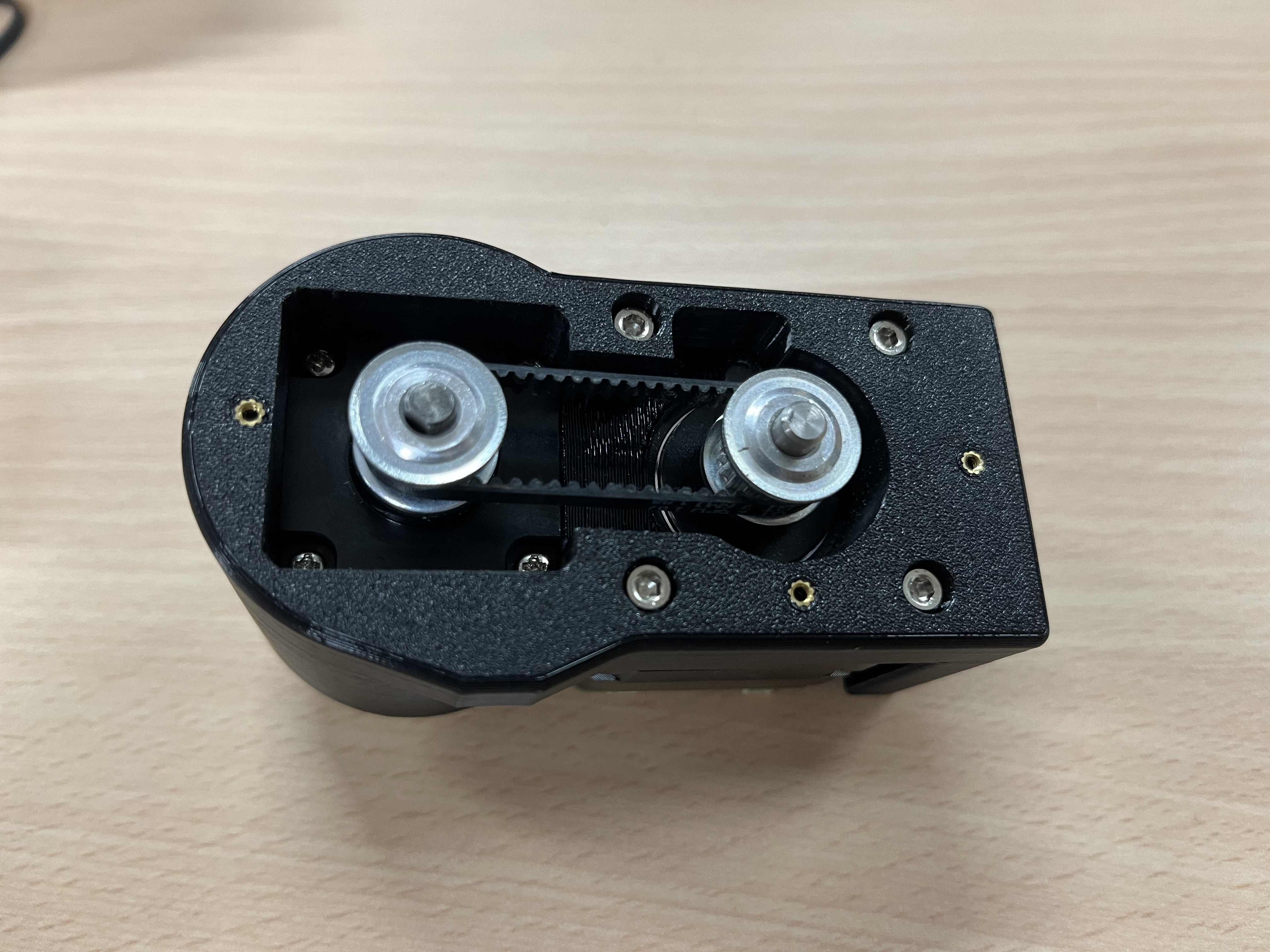
pulleys and Belts
Insert pulleys and belts. Since the belt needs to be tight, each belt should be just enough to fit in, and therefore, the belt needs to be inserted with the pulleys. Remember to tighten the set screws(止付螺絲) on the pulleys to the motor axis.
Full Assembly
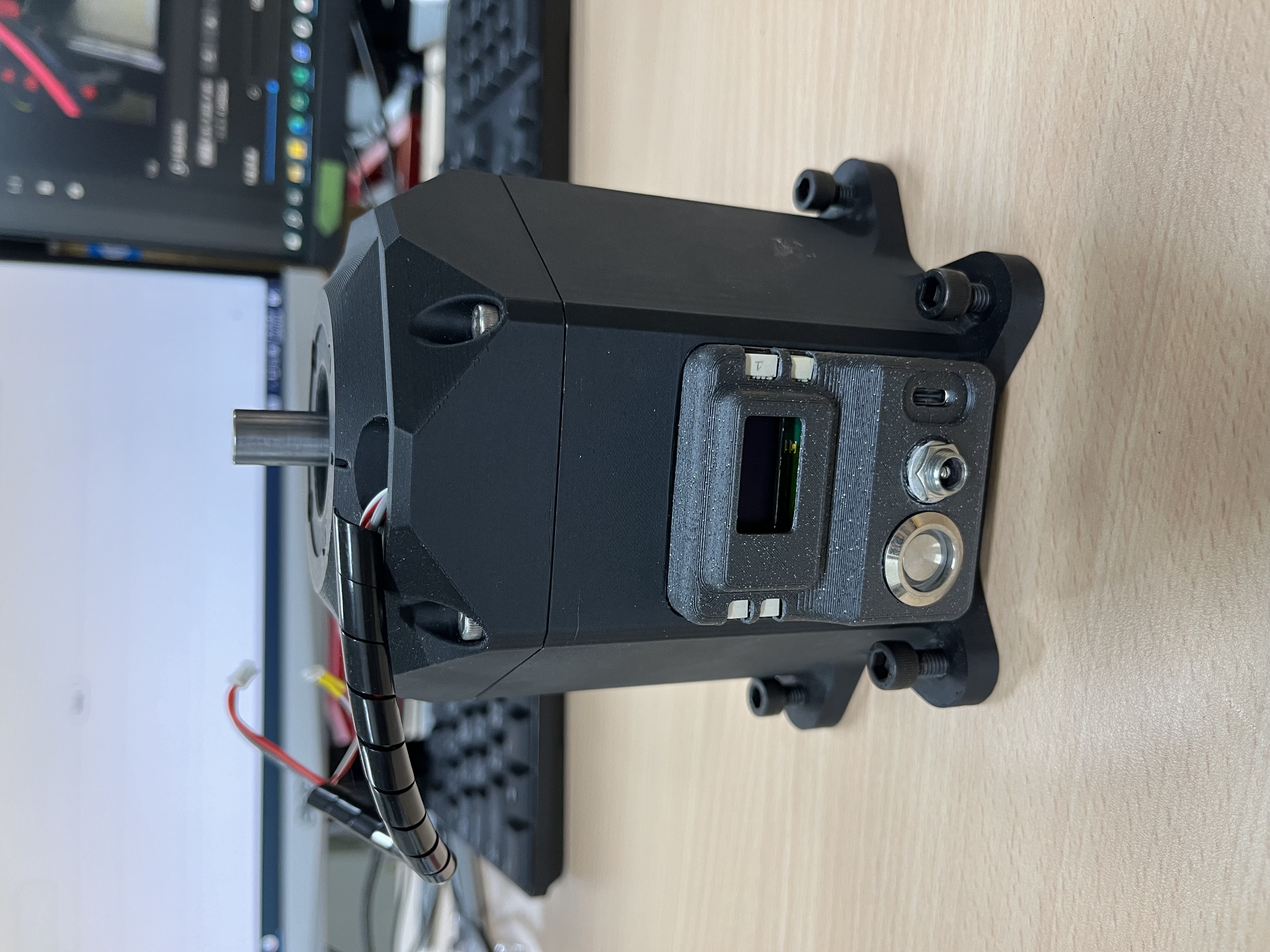
Base
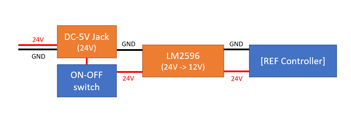
The assembly of the base is slightly complicated. Follow this sequence:
- Tune the LM8596 to transform input 24V to 12V.
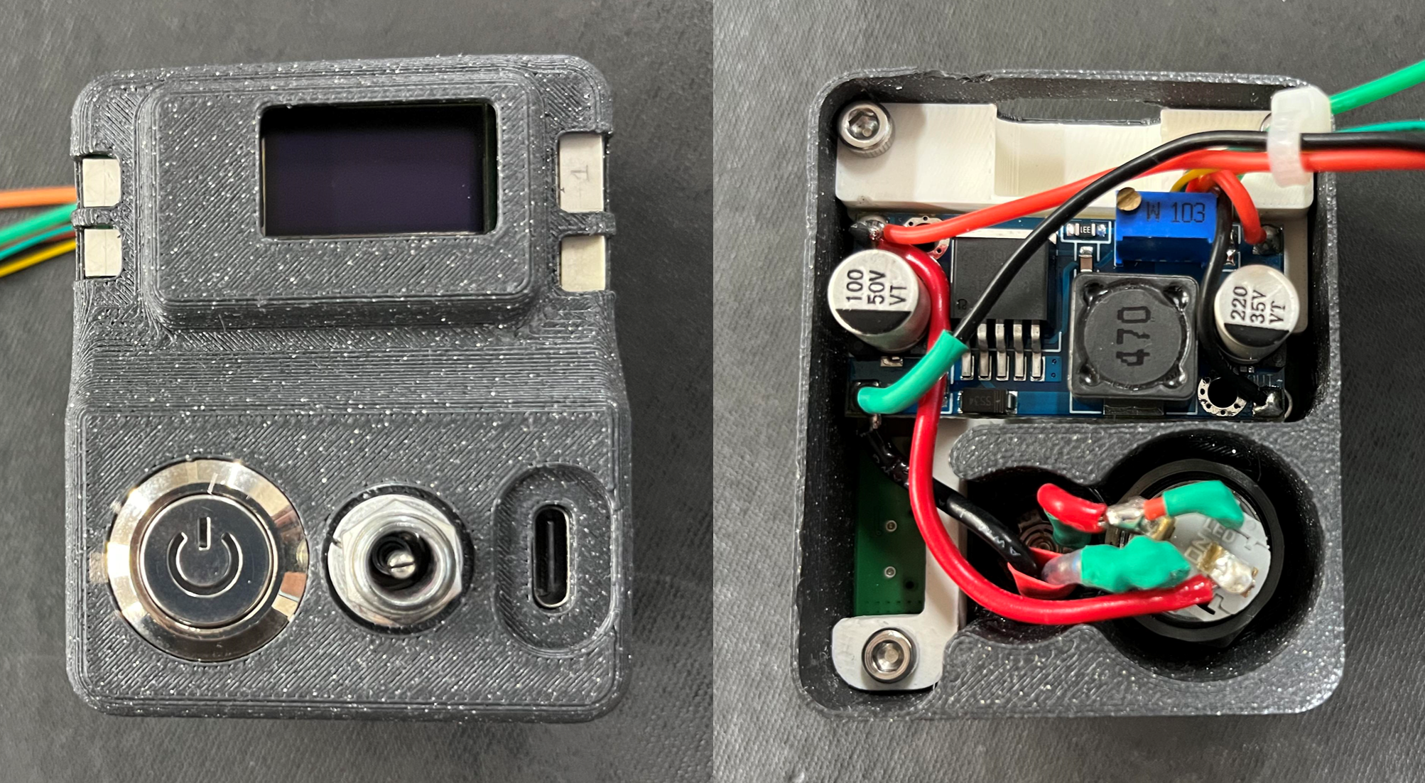
- Controller case assembly:
- Wiring diagram
- Assembly view
- Wiring diagram
- Assemble motor, harmonic drive, and coupler in the middle.
- Assemble motor holder.
- Tug motor holder into the base housing.
- Pull the wire out from the hole.
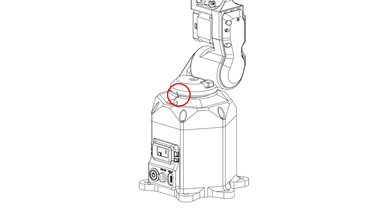
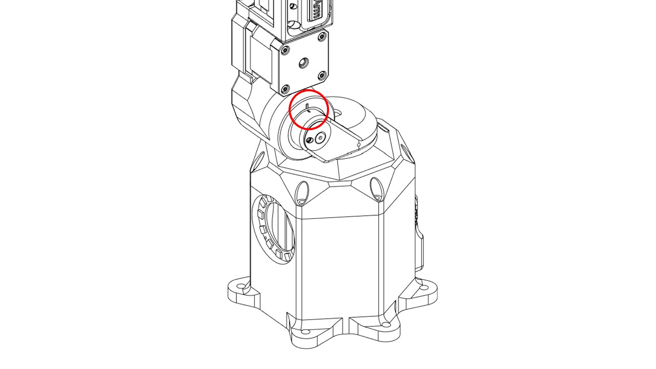
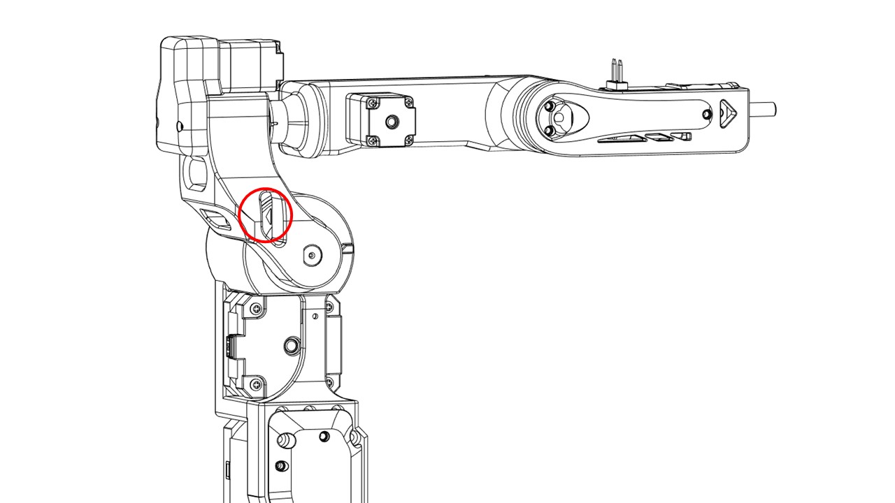
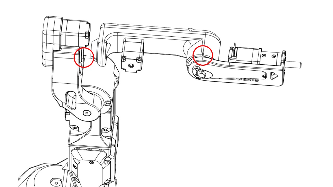
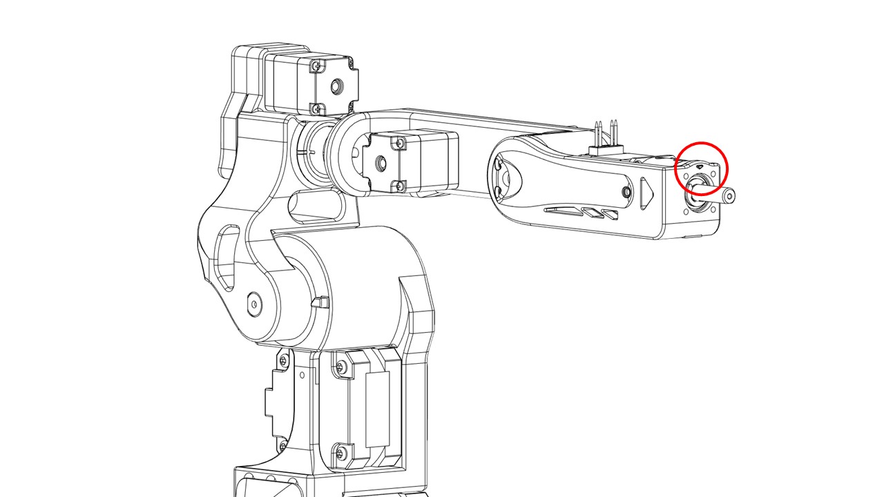
Witness marks
Use witness marks during the calibration process to ensure different components are properly aligned or positioned as per the specified configuration. During assembly, carefully check if the witness marks are aligned.
Assembly sequence
The reference assembly sequence is provided, but you can also create your own sequence:
- Base -> Bottom plate
- Shoulder -> Base
- Arm -> Shoulder
- Elbow -> Arm
-
Wrist -> Forearm
-
full assembly