Troubleshooting
Python Environment
CAN Bus
Can't connect to some joints
If you cannot communicate with some joints, such as when you type:
and the joint doesn't react, there may be issues with the CAN bus communication. Try the following steps:
- Remove and replug the SH-2p connector to check for wire breaks or circuit shorts. Often, unplugging and replugging resolves the issue.
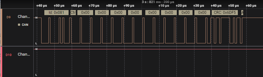
- If the problem persists, use a logic digital signal analyzer to test the signal integrity.
The correct signal should resemble this:
If the signal looks like this, one or more motor boards may be dead or not set up correctly. Try uploading the firmware again or testing each motor board individually.
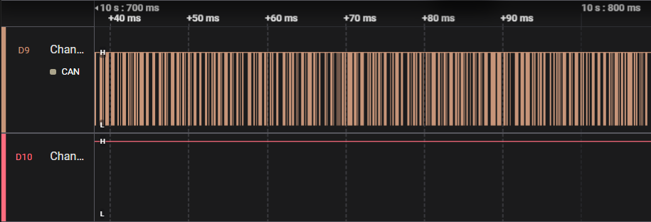
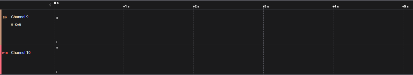
Last if you see this, which means there may be one or more motor boards is dead or they're not setup correctly. Try to upload the firmware again or test them one by one.
CAN debugging
Issues with the CAN bus rarely occur on this robot. Typically, the inability to send CAN bus commands properly is due to poor contact. Reinserting the cables usually resolves this problem. For testing, you can divide the robot into two sections: joints 1 to 3 and joints 4 to 6. On the larger motor control board, there's a switch to adjust the CAN bus termination resistance, allowing you to disconnect the CAN connection between joint 3 and joint 4. Test whether you can control the bottom three axes properly after switching on the termination resistance for joint 3. If successful, the issue likely lies with the top three axes having poor contact. It's not possible to test the top three axes individually due to space constraints on the smaller motor board.
Encoder and Magnet
If you find you can't calibrate the encoder, please check the magnets.
If you can't calibrate the encoder, check the magnets. If the calibration fails, it's likely due to loose magnets behind the motor axis, preventing the encoder from correctly measuring rotation.
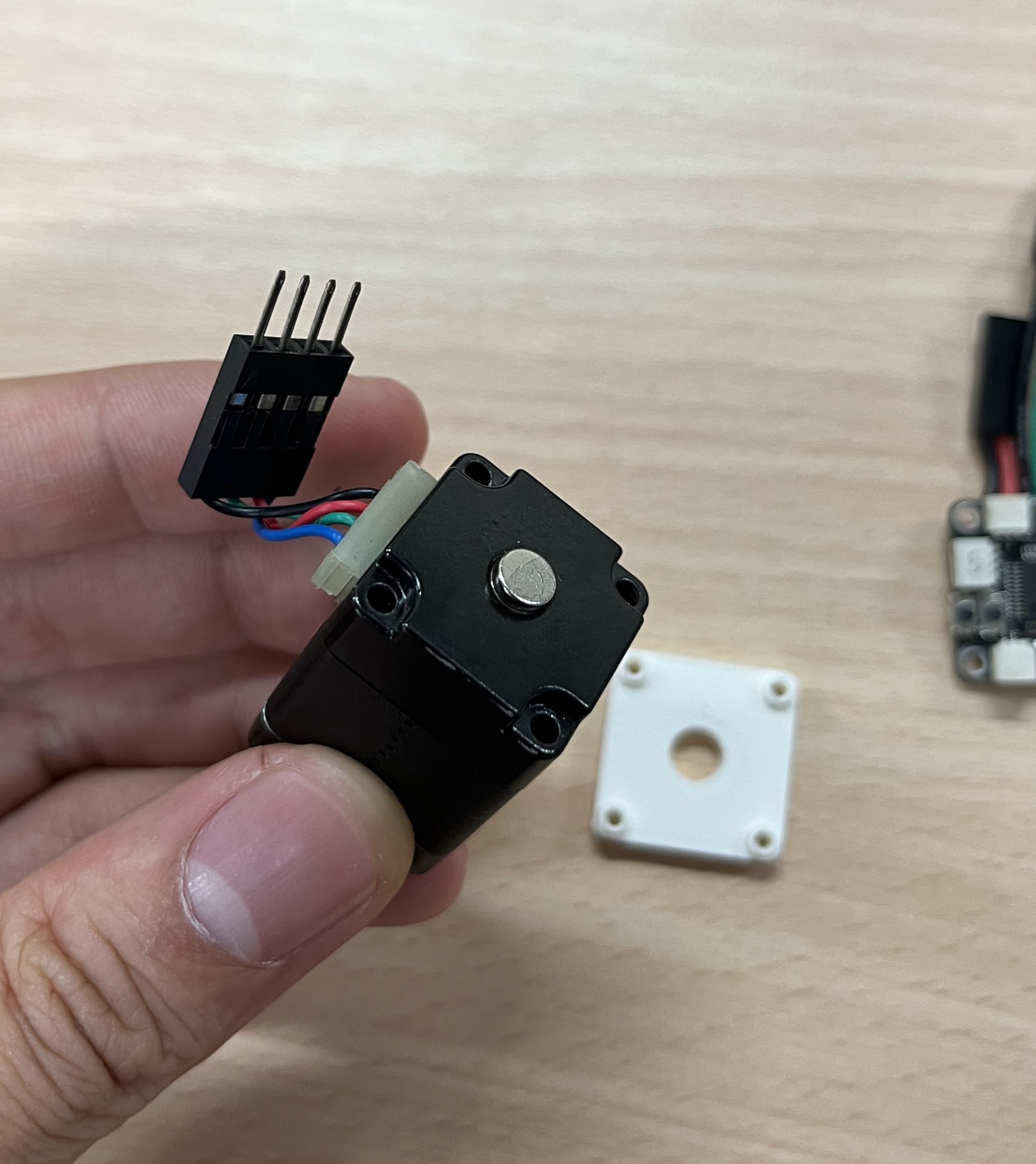
- Remove the screws and PCB at the back of the motor to access the magnets.
- Ensure the magnets are correctly positioned and tightly secured. If not, reglue the magnets to the axis.
- Run the calibration again.
USB
Device not found or wrong drive
If you encounter issues with device recognition, try installing the driver based on here. After installation, you should see the device listed in the device manager.

Motor board ID
find your new ID
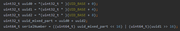
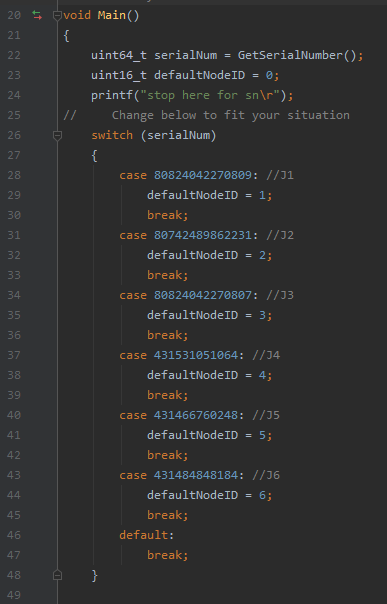
When creating a new motor board, it's crucial to find the motor board ID and set it in the REF board. This ID is how we differentiate between different joint motors.
The original ID is shown here:
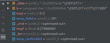
- Using Clion Breakpoint (Recommended): Set a breakpoint at the variable of ID and check its value directly.
- Using STM32CubeProgrammer: Read the memory to find the ID and calculate it manually.
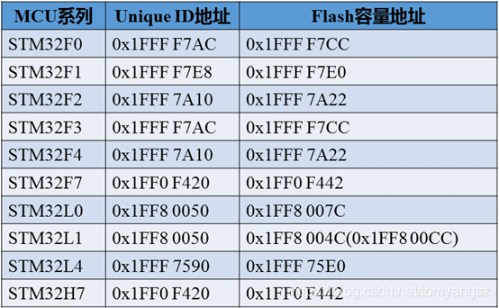
Here's how the ID is calculated: